MOTOR DRIVE
Overview
Numerous motion control applications rely on permanent magnet DC motors due to their ease of implementation in control systems compared to AC motors. These DC motors, whether brushed or brushless (BLDC), offer precise control over speed, torque, or position, making them a popular choice in various applications. Depending on the specific demands of the application, either type of DC motor can be employed with the correct supporting components. The reliability of the motor in these applications is paramount, but the devices that drive these motors are equally as important. Precision control in many motion control applications requires high power analog to generate movement. Designing power circuitry that is highly reliable and highly stable while balancing electrical and thermal management issues can be very challenging. Apex Microtechnology enables the engineer to solve these challenges by offering commercial off-the-shelf (COTS) integrated power modules, power operational amplifiers, and PWM amplifiers designed for motor drive applications.
Whether driving DC brush or brushless motors, Apex Microtechnology offers more than 50 models of high current integrated power modules, power operational amplifiers, and pwm amplifiers with output capabilities ranging from 1 A up to 200 A and wide supply voltage operation as high as 1200 V. These single-package solutions incorporate various integration interfaces including DSP, MCU or analog inputs as well as over-temperature and short circuit protection, and cycle-by-cycle current limit to handle start-up current without de-rating.
Silicon Carbide Integrated Power Module
| Part | Supply Voltage MAX [V] | Output Current CONTINUOUS [A] | Switching Frequency MAX [kHz] | Power Dissipation MAX [W] | Output Architecture |
|---|---|---|---|---|---|
| MSA303 | 650 | 40 | 1000 | 3-Phase | |
| SA111 | 650 | 32 | 1000 | 56 | Single-Phase |
| SA310 | 650 | 30 | 400 | 111 | 3-Phase |
| SA110 | 400 | 20 | 250 | 89 | Single-Phase |
PWM Amplifiers
| Part | Output Current CONTINUOUS [A] | Supply Voltage MAX [V] | Switching Frequency MAX [kHz] | Power Dissipation MAX [W] | Int. Power MAX [W] |
|---|---|---|---|---|---|
| SA03 | 30 | 100 | 23 | 300 | 250 |
| SA160 | 14 | 80 | 45 | 1200 | 156 |
| SA306 | 8 | 60 | 300 | 17 | 100 |
| SA57 | 8 | 60 | 100 | 17 | 100 |
| SA53 | 3 | 60 | 100 | 100 | 100 |
| SA303 | 3 | 60 | 100 | 100 | 100 |
Linear Amplifiers
| Part | Output Current MAX [A] | Supply Voltage MAX [V] | Slew Rate TYP [V/µs] | Standby Current MAX [mA] | Power Dissipation MAX [W] |
|---|---|---|---|---|---|
| PA05 | 30 | 100 | 100 | 120 | 250 |
| PA04 | 20 | 200 | 50 | 90 | 200 |
| PA12 | 15 | 90 | 4 | 50 | 125 |
| PA02 | 5 | 38 | 20 | 40 | 48 |
| PA07 | 5 | 100 | 5 | 30 | 67 |
| PA10 | 5 | 90 | 3 | 30 | 67 |
| PA73 | 5 | 60 | 2.6 | 5 | 67 |
| PA76 | 3 x2 | 40 | 1.4 | 40 | 36 per channel/60 total |
| PA74 | 2.5 x2 | 40 | 1.4 | 40 | 36 per channel/60 total |
| PA75 | 1.5 x2 | 40 | 1.4 | 10 | 19.5 per channel/28.6 total |
Brushless DC Motors (BLDC)
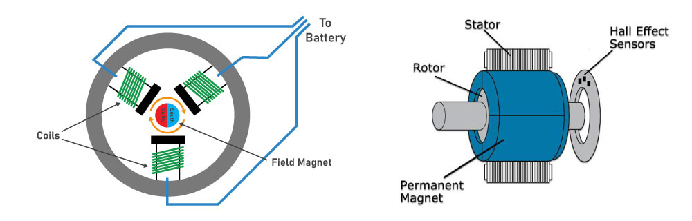
Brushless DC motors operate on the same principles of attraction and repulsion as brushed motors; however, they are constructed differently. Instead of relying on a mechanical commutator and brushes, brushless motors utilize electronic commutation to rotate the magnetic field of the stator, requiring the use of active control electronics. In a brushless motor setup, the rotor integrates permanent magnets, while the stator houses windings. The number of windings, termed phases, in a brushless motor varies, with 3-phase configurations being the most common.
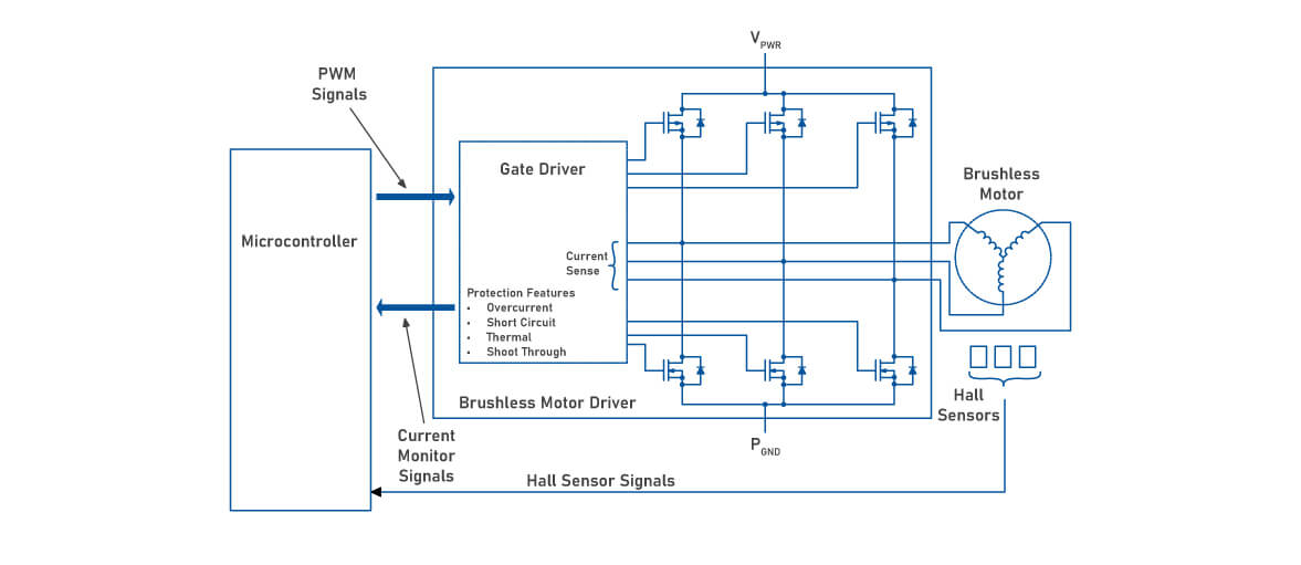
Driving a 3-phase brushless motor requires each phase to alternate between input supply voltage and ground. This is typically achieved using three "half-bridge" drive circuits, each comprising two switches, which could be bipolar transistors, IGBTs, or MOSFETs, depending on voltage and current requirements. Various drive techniques exist for 3-phase brushless motors. The simplest is trapezoidal, also known as 120-degree commutation, which resembles the commutation method used in DC brush motors. More advanced methods such as sine (or 180-degree) commutation offer superior performance by continuously driving current through all three motor phases.
For this, Apex Microtechnology offers a device family of 3-phase PWM amplifiers and Silicon Carbide Integrated Power Modules designed to drive brushless DC (BLDC) and permanent magnet synchronous (PWSM) motors. These devices come with three independent half-bridges easily incorporated into the microcontroller or DSC control. These 3-phase drivers are equipped with protection features such as under-voltage lockout (UVLO) function and active miller clamping to reduce switching noise and improve reliability.
Brushed DC Motors
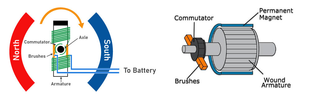
DC motors utilize wound coils of wire to generate a magnetic field. Within a brushed motor, these coils are free to rotate, constituting the "rotor" responsible for driving the shaft. Typically, the coils are wound around an iron core; however, there are brushed motors that are "coreless", delivering self-supported winding. The stationary component of the motor is known as the "stator", which employs permanent magnets to establish a fixed magnetic field. To induce torque and initiate rotor motion, the magnetic field of the rotor must continuously rotate, attracting and repelling against the fixed stator field. Achieving this rotation involves a sliding electrical switch, comprised of a commutator and fixed brushes. As the rotor revolves, different sets of rotor winding are constantly switched on and off by the commutator, making the rotor spin.
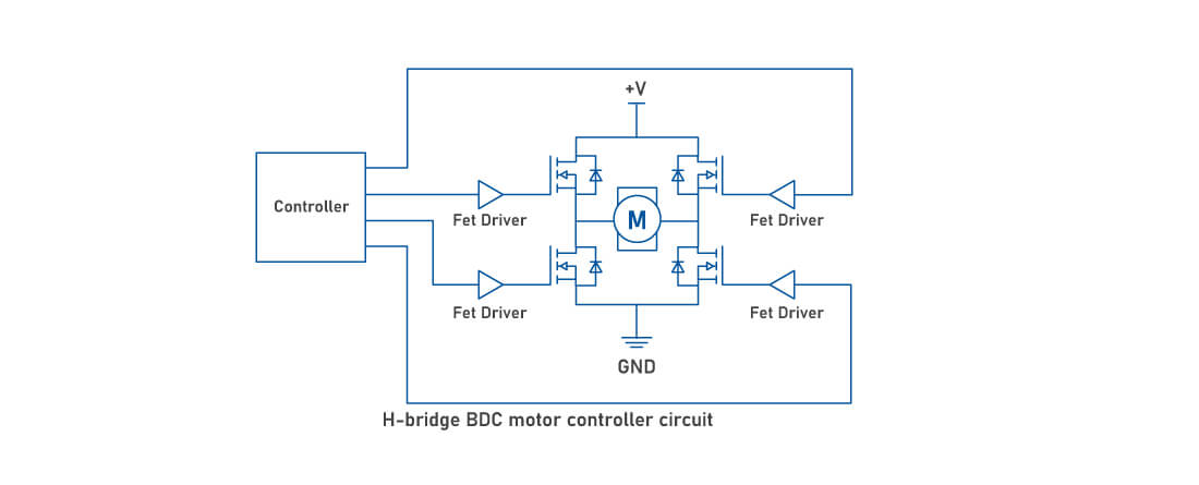
To power a brushed motor, DC voltage is applied across the brushes, enabling current flow through the rotor windings to initiate motor movement. For total control over speed, torque, and direction, an "H-bridge" composed of electronic switches - transistors, IGBTs, or MOSFETs - is used to allow bidirectional motor operation. The motor speed or torque can be controlled by pulse width modulating (PWM) one of the switches. Most brushed motors use PWM controllers that utilize H-bridge circuitry consisting of two high-side and two low-side switches. For example, when the motor needs to increase speed, the controller increases the duty cycle (the ratio of the pulse to the pulse period). The new PWM signals arrive at the gate drivers, opening the transistors for an extended period of time to let more current in. To rotate a BDC motor in one direction, the controller diagonally opens the H-bridge switches. The switching process comes with delay, so while reversing the rotation of the motor, all four transistors may be turned on. To prevent current and voltage leakages, dead time can be added which allows the controller to keep all transistors closed and open during turns.
At Apex Microtechnology, we have designed high voltage and high current devices that do this for you, featuring integrated gate driver logic with dead-time generation and shoot-through prevention. Apex's diverse product portfolio of linear amplifiers, PWM amplifiers, and SiC integrated power modules are designed to meet the diverse demands of modern motor drive applications. Seamlessly incorporated into motor drive systems, our solutions ensure optimal performance, efficiency, and reliability.